Error message
To log in to this site, your browser must accept cookies from the domain www.mill-max.com.Introduction to IC and TO Sockets
Integrated Circuit (IC) Sockets
Mill-Max complements high speed-turning with a comprehensive selection of pre-tooled "multi-finger" spring contact clips. Female receptacles are made by press-fitting one of these contacts into a precision machined shell.
- All machined IC sockets accept .015" - .025" (0,38 - 0,64) dia. and standard IC leads.
- Hi-Rel, 4-finger BeCu inner contact rated at 3 amps.
- Contact pins are manufactured for High-reliability - 2 piece construction
- Gas tight seal - Environmental conditions will not affect the integrity of the contact.
An IC socket, or integrated circuit socket, is a tool that connects an integrated circuit (IC, also commonly referred to as a chip,) to a printed circuit board (PCB).
IC sockets are used to:
Test ICs
IC sockets are used to evaluate the reliability, functionality and electrical characteristics of ICs. They are designed so that IC devices can be plugged in and removed from them, allowing multiple ICs to be repeatedly evaluated.
Prevent Damage
IC sockets protect ICs from damage that may occur during soldering and desoldering chips directly to and from a PCB, extending the life of the IC and the PCB. Some IC’s are especially susceptible to being damaged by exposure to heat, even for the short period of time it takes to pass through a soldering process. These types of chips benefit greatly from being plugged into an IC socket after the PCB has gone through its soldering processes.
Replace Damaged ICs
IC sockets allow faulty or failing ICs to be easily replaced without damaging the PCB.
IC sockets can be mounted in three ways:
Surface Mounting: | These are IC sockets that are soldered directly to the surface of a substrate onto lands or pads. These types of IC sockets typically have gull-wing or stub tail leads designed to solder onto PCB pads. This method is widely used for high-performance, double sided, densely populated PCB’s and miniaturized electronic components. |
Through-Hole Solder Mounting: | These are IC sockets having solder tails which are designed to pass through a PCB hole and accept solder to attach them. This method is often used in lower density, larger assemblies and typically with single sided PCBs. |
Press-fit Mounting: | These are IC sockets designed to be press-fit into PCB holes, making electrical connection without the need of soldering. The leads on these sockets may have square, triangular or other polygon features that are designed to press into the plating of the PCB hole to make the mechanical and electrical connection. Another style is the compliant press-fit tail which is designed to be flexible to accommodate the tolerance of a standard PCB plated-thru-hole. When the compliant tail is pressed into the hole it conforms to the hole size while biting into the plating of the hole making a reliable connection without damaging the PCB hole. |
Single Inline Package (SIP) Strip
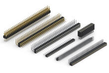
Single inline Package or SIP is the most basic packaging style for an IC. SIP sockets are interconnect components that consist of a rectangular insulator populated with receptacles designed to accept the most common lead sizes of SIP IC’s. Mill-Max also manufactures SIP male pin, and spring-loaded headers for a multitude of board-to-board or wire-to-board interconnect options. Pitch/pin-to-pin spacing options range from 1mm (.0394”) to 4mm (.1575”), including single, double, and triple row options as well as different termination styles such as through hole, SMT, wire termination and press-fit.
Dual Inline Package (DIP)
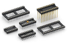
Dual inline package or DIP IC’s have long been the most popular packaging style for integrated circuits. DIP sockets are interconnect components that consist of a rectangular insulator with two parallel rows populated with receptacles designed to accept the most common lead sizes of DIP IC’s. Mill-Max also manufactures DIP headers for board-to-board and wire-to-board interconnect configurations. The standard pitch/pin-to-pin spacing for DIP IC’s is .100” (2.54 mm), The distance between the parallel rows is more varied, spacing options include .200” (5.08 mm), .300” (7.62 mm), .400” (10.16 mm), .600” (15.24 mm) and .900” (22.86 mm). .070” pitch spacing options are offered for shrink DIP package applications. DIP sockets and headers are available in a variety of termination styles including solder tail, SMT, wire termination, and press-fit options.
Pin Grid Array (PGA)
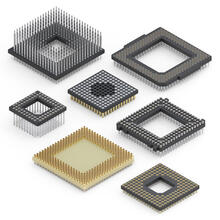
A type of processor packaging which offers high-position, customizable arrays of pin/receptacle connections, typically with a straight or interstitial .100” (2.54mm) pitch, and housed in a square or rectangular insulator. Mill-Max offers PGA style headers, sockets, and carriers for surface mounting, through-hole mounting, or wire-wrap termination. Mill-Max Pin Grid Array sockets are designed to accept high pin count IC's, using low force 6-finger contacts to ease insertion/extraction of the device. Our standard low force #32 contact is used for pin counts up to 150, our ultra-low force #35 contact is recommended for 150 pins or more but less than 250 pins. The "ultra lite" #43 contact is recommended for 250 pins or more.
Ball Grid Array (BGA)
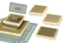
A surface mount packaging for integrated circuits (ICs) such as microprocessors. The bottom of the package features a high-density array of solder balls or preforms to make connections to a PCB. Mill-Max offers a two-piece adapter system for making BGA devices pluggable; This consists of a male header which mounts to the preforms on the underside of the BGA, as well as a female socket, soldered to the PCB, to mate with the header. Standard pitch options are .8mm, 1mm, and .050”.
PLCC Socket
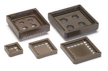
Mill-Max offers a variety of PLCC sockets for both through-hole and surface mount applications.
- Accepts JEDEC PLCCs MS-016, MS-018, MO-047 & MO-052 leaded plastic substrates.
- Insulator material is glass reinforced PPS Rated UL94V-0.
- Low profile for high density PC board stacking available.
- Standoffs provide clearance for heat dissipation and cleaning.
- Internal standoffs insure proper positioning of chip carrier in socket.
- Contacts are plated with 150μ” tin.
- Pre-lubricated and Tape & Reel available.
Transistor Socket (TO)
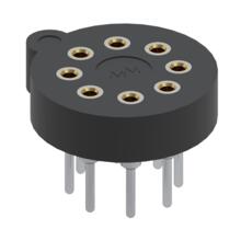
The leads on many of the most popular through hole transistors are arranged in a circular pattern having 3, 4, 8 or 10 leads are different size bolt circles. TO Transistor sockets are designed to make the replacement of these transistors easy and convenient, especially in the field. If a transistor fails or if one needs to be upgraded, a transistor socket simplifies the process by eliminating the need to desolder the old and solder the new device in its place. The diameters and spacings are pre-determined to meet most standard package types, namely adhering TO-5 and TO-100 footprint requirements. TO transistor sockets are offered in both through hole and surface mount termination options.


